
Let’s take one other take a look at our circuit and add a helpful element that can permit us to rapidly and simply management the worth of our aim coordinate for our venture: a joystick! We will use the up-down axis of the joystick to extend and reduce the worth of our y variable, which strikes our robotic up and down, and use the left-right axis of the joystick to extend and reduce the worth of our x variable, shifting our robotic from left to proper.
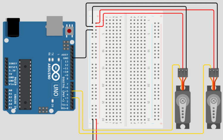
Join the constructive voltage pin of the joystick to the 5V pin on the Arduino, by means of the ability rails of the breadboard. Join the GND pin to the GND rail of the breadboard, and the x and y pins of the joystick to the A0 and A1 pins on the Arduino.
Now that we’ve wired all of the elements we’ll want, the ultimate step can be changing our inverse kinematics equations into code and including within the few traces we have to learn our joystick values! Fortunately, Arduinos are nice at math and have capabilities for every of the mathematical operations we’ll want to finish the calculations constructed into the programming language.
#embody "Servo.h"
Servo servoOne;
Servo servoTwo;
//Establishing our IK variables
double x = 30.0;
double y = 120.0;
double linkOne = 100.0;
double linkTwo = 100.0;
double alphaOne;
double alphaTwo;
double alphaFinal;
double betaOne;
double betaTwo;
double betaFinal;
double c;
double d = 60.0;
double e;
int xval;
int yval;

void setup() {
  Serial.start(9600);
  servoOne.connect(3);
  servoTwo.connect(5);
}

void loop()
{
  //IK Calculations
  yval = analogRead(A0);
  xval = analogRead(A1);
  c = sqrt((x*x)+(y*y));
  e = sqrt(((d-x)*(d-x))+(y*y));
  alphaOne = atan(y/x) * (180/PI);
  alphaTwo = acos(((linkTwo*linkTwo)-(c*c)-(linkOne*linkOne))
            /(-2*linkOne*c)) * (180/PI);
  betaOne = atan(y/(d-x)) * (180/PI);
  betaTwo = acos(((linkTwo*linkTwo)-(e*e)-(linkOne*linkOne))
            /(-2*linkOne*e)) * (180/PI);
  if(x < 0){ alphaFinal = 180 + ((alphaOne) + (alphaTwo)); betaFinal = 180 - ((betaOne) + (betaTwo)); } else if(x > d){
      alphaFinal = ((alphaOne) + (alphaTwo));
      betaFinal = -1 * ((betaOne) + (betaTwo));
    }
  else{
      alphaFinal = ((alphaOne) + (alphaTwo));
      betaFinal = 180 - ((betaOne) + (betaTwo));
    }

  //Printing the outcomes!
  Serial.print("alpha One: ");
  Serial.print(alphaOne);
  Serial.print(" beta One:");
  Serial.print(betaOne);
  Serial.print(" alpha Two: ");
  Serial.print(alphaTwo);
  Serial.print(" beta Two:");
  Serial.print(betaTwo);
  Serial.print(" Alpha: ");
  Serial.print(alphaFinal);
  Serial.print(" Beta: ");
  Serial.println(betaFinal);
  servoOne.write(alphaFinal);
  servoTwo.write(betaFinal);

/*
Relying in your customization, it could be a good suggestion so as to add some limits right here! For those who see your arms appearing squirrely, add a press release  akin to “if(xVal > 800 && xVal < 200)” */ if(xval > 800){
    x-=5;
  }
  if(xval < 300){ x+=5; } if(yval > 800){
    y-=5;
  }
  if(yval < 300){
    y+=5;
  }
}
Let’s break down the code we simply despatched over to our Arduino. One of many first issues our code accomplishes is creating variables for our aim place on our grid within the type of a set of x and y coordinates. On this case, the coordinates (30, 120) have been chosen in order that the robotic begins within the heart of the grid. These values will be modified to have the pen begin wherever on the grid you’d like! Subsequent, we will create the remainder of the variables we’d like for our calculations. Every step of the equations has its personal variable throughout the code.
The variables linkOne and linkTwo symbolize the lengths of the hyperlinks in our system, that are each 100 mm. Subsequent, the variables alphaOne, alphaTwo, alphaFinal, betaOne, betaTwo, and betaFinal symbolize all our sub-angle and final-angle variables. Lastly, the c and e variables are our theoretical triangle traces, and d represents the space between the shafts of our two actuators.
Now that we’ve all the mandatory variables, we will start changing our inverse-kinematics equations into code. Although these traces of code may look rather more difficult than a few of our earlier traces of code, should you undergo them step-by-step, you’ll see that we’re taking every motion we developed in our equations and changing it into code our Arduino can perceive.
As soon as we’ve values for all our variables and have accomplished our major calculations, all that’s left is to mix our sub-angle variables into final-angle variables that can be despatched to our actuators. As you could recall from our earlier calculations, a few of our final-angle calculations are depending on the worth of our x variable. Fortunately, three units of conditional statements are all we’d like to ensure our angles are being calculated accurately, it doesn’t matter what x and y values are chosen.