
Solely the feminine half of the servo extension cable is required. Lower the feminine connector from the cable together with about 2″ of its wires. Solder its energy and sign wires to the Feather’s Bat and D13 pins, respectively, and depart the bottom wire unsoldered for the second.
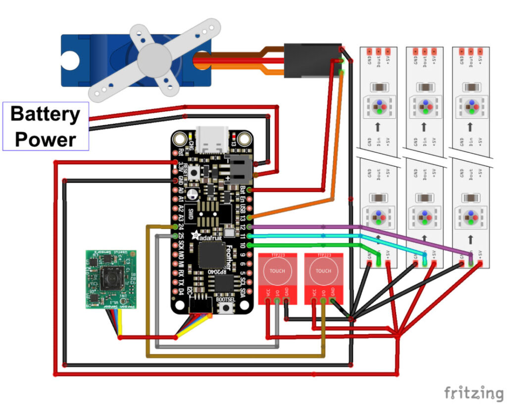
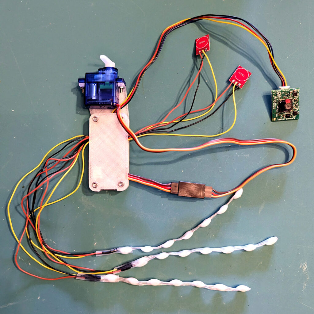
The wired connections between the Feather RP2040 and its peripherals are proven in Determine S. The Feather’s 3V and GND pins present energy for 3 LED strings and two contact sensors.
To simplify the connections, we’ll solder the peripherals’ energy wires collectively in two bunches for energy and floor, then join every bunch to a single section of strong core wire which then connects to a single Feather pin. Lower two 1″ lengths of twenty-two AWG strong core wire and strip about 1cm of insulation from one finish of every wire. Group the 30 AWG energy wires from the capacitive contact sensors and LED strings collectively, stripping about 1cm of insulation from their ends. Twist the stripped ends collectively. Do the identical with the bottom wires from the contact sensors and LED strings, together with the servo cable’s floor wire on this bunch. When twisting the wires collectively, attempt to decrease tangling and knotting. Tin the twisted bunch of energy wires, then solder it to the stripped finish of one of many strong core wire items. Slide a bit of shrink tube over the joint and warmth to shrink.
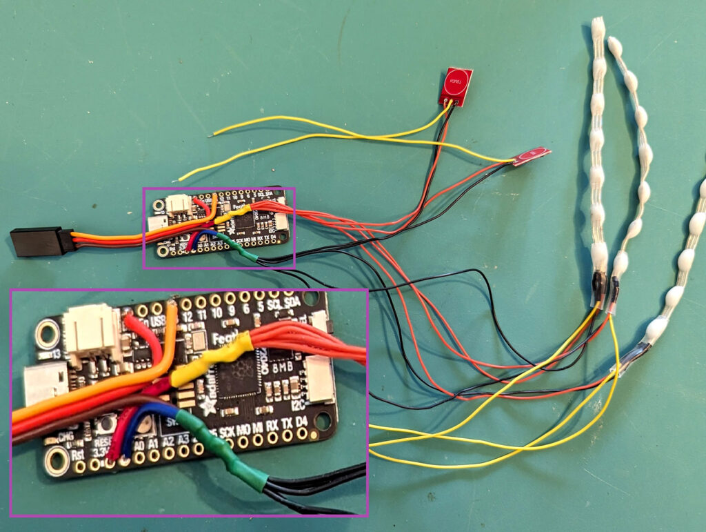
Repeat the identical steps to attach the bunch of 30 AWG floor wires and the servo cable floor wire to the remaining piece of strong core wire. Lastly, solder the free ends of the strong core wire items to the 3V and GND pins on the Feather 2040. At this level, the wiring ought to resemble Determine T.
Subsequent, solder the free ends of the contact sensors’ sign wires to Feather pins D24 and D25, and the LED strings’ sign wires to Feather pins D10, D11, and D12.
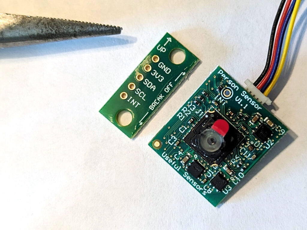
Take the Individual Sensor, and punctiliously use pliers to snap of the portion of the board labelled “break off” (Determine U). Join the Stemma QT cable to the corresponding connectors on the Feather and the Individual Sensor.
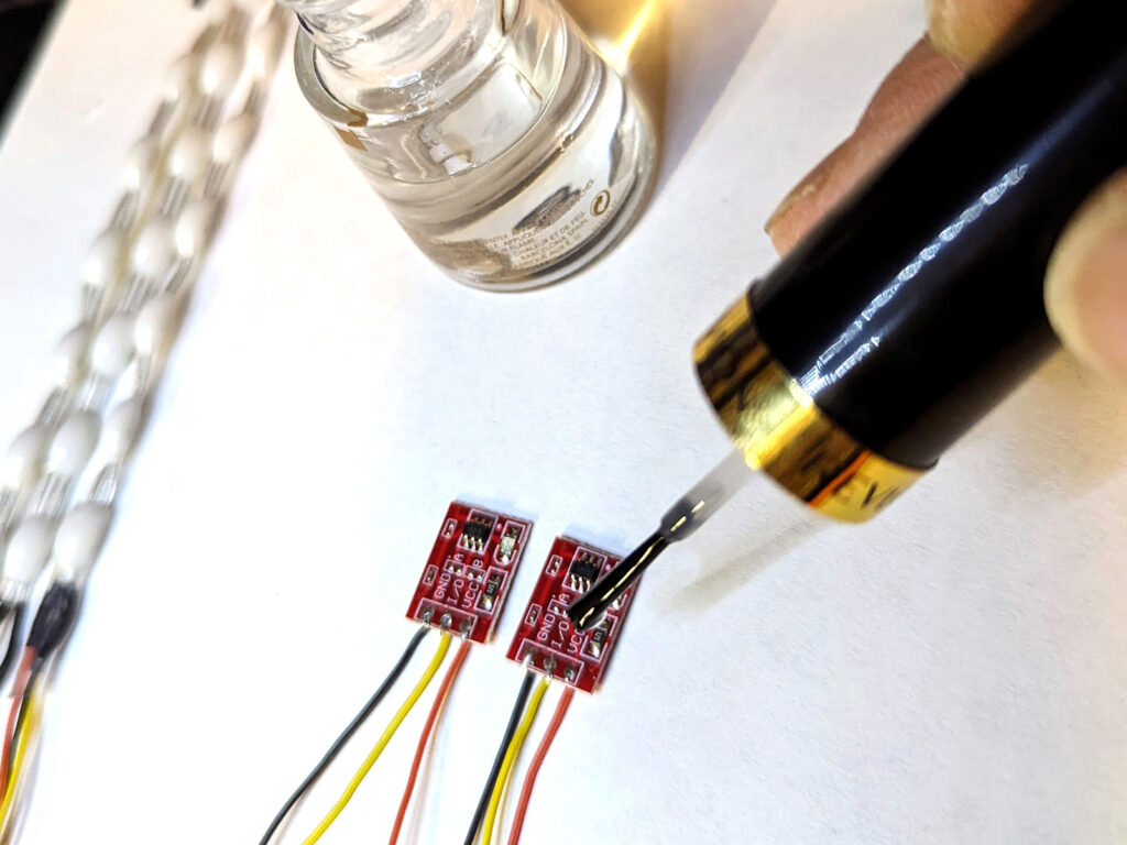
We’ll coat the sensor boards with clear nail polish for an additional layer of safety and insulation. Take the contact sensors and paint a layer of polish over the whole aspect containing the tiny SMT parts (Determine V). Let the polish dry for 10 minutes. On the other aspect of the contact sensors, paint a little bit of polish over the solder pins solely, avoiding the portion of the board with the phrase “contact.”
Equally, apply a coat of clear polish over the floor mount electronics on either side of the Individual Sensor, being cautious to not paint the digicam lens or the Stemma QT connector.
When the polish has dried completely, insert the Feather into the 3D-printed enclosure, with the peripheral wires extending from the enclosure’s aspect holes. Safe the lid to the bottom with the 4 12mm M2 screws and nuts as proven in Determine W.
Connect the micro servo to the 2 vertical prongs on the 3D-printed case with the 8mm M2 screws and nuts as proven. Orient the servo so its output shaft is centered alongside the brief finish of the enclosure lid. Connect the single-ended horn to the shaft in order that the horn factors straight upward in the course of its rotation vary, then screw the horn firmly onto the servo. Plug the servo connector into the feminine connector extending from the Feather.